A broadcast studio LED backdrop is a fine-pitch LED video wall — typically P1.2 to P2.6 — installed behind presenters and frame-locked to the broadcast cameras via genlock so that no scan-line artefacts reach air. The specification does not start with screen size. It starts with camera distance, lens choice, frame rate and how much of the wall will be sharp in shot. Pixel pitch matters, but only as part of a system: LED processor, camera shutter, refresh behaviour and studio lighting have to be designed together. Get any one of them wrong and the symptoms appear on camera as moiré, colour shift or rolling scan lines — usually during a live programme, which is the worst possible time to discover them.
Key Takeaways
- Pixel pitch for broadcast backdrops typically falls between P1.2 and P2.6, set by the closest camera position, the lens and whether the wall is held in sharp focus — not by wall size.
- Genlock between the LED processor and the camera system eliminates rolling scan artefacts. It is not optional on any broadcast-grade installation, and the sync plan should be agreed before hardware is ordered.
- Refresh rates of 3,840 Hz or higher give the camera enough sampling headroom to avoid banding and flicker at every standard broadcast frame rate.
- Camera pairing matters as much as the LED specification: shutter angle, frame rate, sensor readout and lens choice all change what the viewer sees.
- Fixed studios need front-service cabinets under 50 mm deep with redundant power and data paths. Rental panels are engineered for repeated assembly, not for the sustained-run thermal and maintenance demands of a permanent set.
- A test shoot at the real frame rate and shutter angle is almost always cheaper than changing the wall after installation.
Broadcast Studio LED Backdrop Specification
| Parameter | Typical Broadcast Range |
|---|---|
| Pixel pitch | P1.2 – P2.6 |
| Refresh rate | 3,840 Hz minimum |
| Colour depth | 13-bit greyscale or higher |
| Brightness (studio use) | 400 – 800 nits operating |
| Colour space target | Rec. 709 / Rec. 2020 |
| Sync method | Genlock (processor-to-camera) |
| Processor compatibility | Brompton Tessera or NovaStar MCTRL |
| Cabinet depth | 37 – 50 mm (flush-mount) |
| Maintenance access | Full front service preferred |
| Recommended product | DFC Series (COB Flip Chip: DFC 1.5 at 1.58 mm or DFC 1.9 at 1.9 mm); DYF Series (0.93 mm or 1.25 mm) for tighter shots |
Treat these figures as a specification framework, not a substitute for camera testing. Two walls with the same pitch and headline refresh rate can behave differently at low brightness because of driver behaviour, scan configuration and processor settings. The assessment has to cover the complete signal path — from graphics playback and reference timing through to the receiving cards and the camera output.
What Pixel Pitch Does a Broadcast Studio LED Backdrop Need?
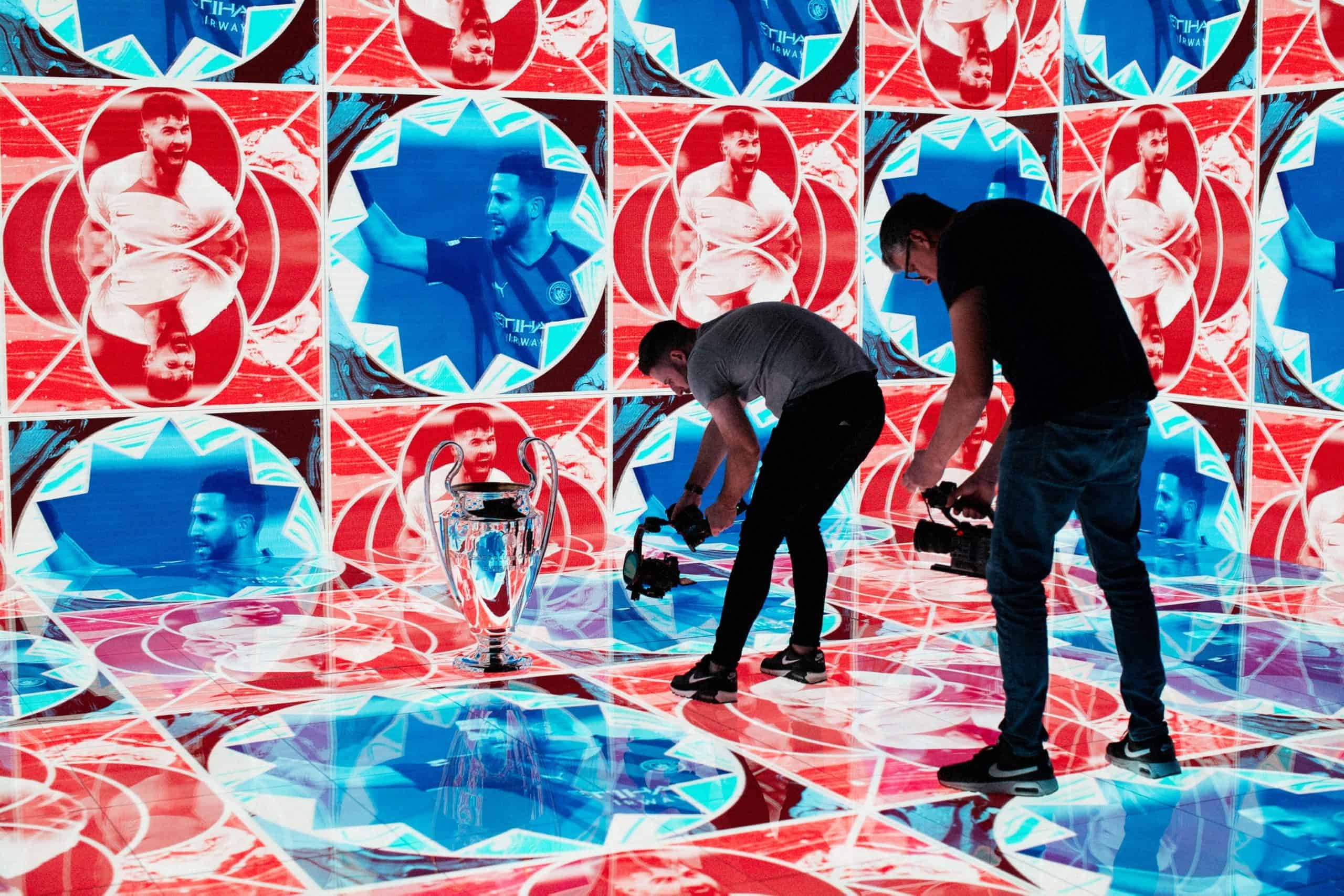
The common mistake is asking “what pitch do we need for this wall size?” The better question is “what is the closest point at which the LED surface will be in focus, and what lens will see it?”
Pitch problems on camera are really focus problems. A 2.6 mm wall works well as a background when the presenter stands several metres in front of it and the director keeps the wall slightly soft — the pixel structure dissolves into the image. The same wall looks wrong the moment a camera pushes in, stops down and pulls the LED surface into sharp focus behind a guest. A 1.5 mm wall buys more freedom to move cameras and hold focus deep, but it also raises cost, processing load and the demands on thermal and service planning.
Moiré follows the same logic. It is an interference pattern between two regular grids — the wall’s pixel array and the camera sensor’s photosite array — and it appears when the lens resolves the pixel grid near the sensor’s own sampling frequency. Tighter pitch, softer focus or a change of camera position all break the interference; turning the brightness down does not. That is why a wall that looks clean from the main camera position can shimmer on a side camera sitting a metre closer at a different angle.
For a newsroom set where presenters sit 2 to 4 metres from the wall, P1.5 to P1.9 delivers a clean image with no visible pixel structure on a typical broadcast lens. Move the camera in for a tight over-the-shoulder shot at 1.5 metres and you need to drop below P1.2 to keep the grid invisible.
Our DFC Series fixed-install panels are built for exactly this application. The DFC runs COB Flip Chip LEDs at 1.58 mm (DFC 1.5) and 1.9 mm (DFC 1.9), in a cabinet just 37 mm deep — thin enough to mount directly to a stud wall without building a deep recess into the set. Full front maintenance means every module, power supply and receiving card is accessible from the studio floor, which matters when the broadcast studio LED backdrop sits against a structural wall with no rear void and no crawl space.
That service model needs coordinating before the supporting structure is fabricated: access clearances, scenic finishes, cable routes and module removal paths all have to be agreed with the set builder. The wall must also finish flat across cabinet seams — small alignment differences catch studio light and become visible during lateral camera moves, even when they are invisible to the eye from the floor.
Resolution scales with wall size, not just pitch. A 4 metre wide by 2.25 metre high wall at P1.5 delivers a resolution comfortably above 1080p and is usable as a 2K source in the gallery. Pushing to full 4K resolution on an LED wall needs either a larger wall or a sub-1mm pitch. We cover the maths behind resolution and viewing distance in separate guides.
Genlock: Why Sync Matters More Than Brightness
Colour and resolution count for nothing if the LED processor and camera are not frame-locked. Without lock, the camera shutter catches the wall mid-refresh, and the result on air is rolling horizontal bands drifting through the picture.
Genlock solves this by slaving the LED processor’s output timing to the studio’s master reference — typically tri-level sync for HD facilities or black burst in older plants — so the wall refreshes in perfect step with every camera on the floor. When the timing relationship holds, each frame the camera records contains a complete image with no partial-refresh boundary in shot. Genlock is necessary, but it is not a cure for every camera artefact: processor phase, LED scan configuration, camera shutter behaviour and the timing of upstream graphics sources still need checking during commissioning. A small phase offset between wall and shutter often needs dialling in — a processor that exposes its sync timing in the UI makes that a five-minute job rather than an afternoon of trial and error.
A good genlock plan starts before hardware is ordered. We check:
- House sync availability, format and distribution to the LED processor position.
- Whether the processor accepts the required reference natively.
- Camera shutter mode, shutter angle and sensor scan behaviour (rolling versus global).
- Whether graphics playback, switchers and conversion equipment are locked to house reference or free-running.
- Processor latency where presenters interact with content or talent monitors mirror the wall.
- Redundancy — spare processor, dual data paths — where the studio cannot lose the broadcast studio LED backdrop during a live programme, and whether the backup route can be tested without interrupting production.
We default to Brompton Tessera for broadcast because its sync and latency reporting is visible in the processor UI, which makes chasing scan artefacts during commissioning far quicker. NovaStar MCTRL is a strong alternative where the facility already runs that ecosystem or the input/output count suits it better. Both are proven in broadcast; the difference is workflow, not capability.
The DFC Series runs at 3,840 Hz — roughly 64 complete refresh cycles per frame of a 60 Hz broadcast feed. That headroom means the camera can sample the wall at any standard frame rate (25, 29.97, 50, 59.94) without landing on a refresh boundary. In an IP facility built on the SMPTE ST 2110 suite, PTP provides the timing backbone for media flows — and the LED processor, gateways and reference conversion still need to be designed into that synchronisation architecture rather than bolted on afterwards.
If you are specifying a broadcast studio LED wall and the word “genlock” has not come up in the conversation, ask the question. It is the single most overlooked specification in studio LED projects. We have seen an integrator spend serious money on sub-1mm pitch panels and then run them without frame sync because “it looked fine on the monitor in the green room.” It looked fine because the green room monitor was not a broadcast camera shooting at 1/50s. The moment they went live on a sport analysis set shooting 50i, the scan lines appeared. Sign-off belongs on the production camera feed and waveform monitor, not on a confidence monitor.
Colour Accuracy and Camera Pairing
Colour work on a studio wall happens in stages. First you calibrate the wall itself — uniform brightness and colour temperature across every cabinet, so no seam or batch difference reads on camera. Then you match the wall’s output to the camera’s colour science, so that what the gallery monitor shows is what the sensor actually records. Finally you assess wall, lighting and camera together, with presenters at their working marks and representative content running.
Most broadcast cameras operate within the Rec. 709 colour space for HD, or Rec. 2020 for UHD and HDR production. The LED processor needs to map the wall’s native gamut — which is wider than either — down to the same target. Skip this step and reds that look accurate to the naked eye can appear oversaturated or hue-shifted on camera. It is a common failure when panels calibrated for direct-view exhibition work are repurposed for broadcast without adjustment: the eye and the sensor do not weigh an LED’s narrow-band spectrum the same way.
That narrow-band spectrum is also why measurement equipment matters. A spectroradiometer reads the actual spectral power distribution of the wall; a handheld colorimeter applies filter approximations designed for broadband sources and can mis-report LED primaries. Calibrating a broadcast wall with the wrong instrument bakes the error into every shot.
COB Flip Chip construction helps on camera. Because the chip-on-board structure removes the dark gaps between discrete SMD packages, the emitting surface is more continuous — smoother colour transitions, more consistent luminance across the panel face, and a higher-contrast black between content elements. For broadcast, that translates to fewer hotspots and a more predictable response when the camera’s auto-exposure and white-balance systems interact with the wall.
Camera pairing extends beyond colour. A rolling-shutter sensor can reveal artefacts that a global-shutter camera never shows. Long lenses compress the scene and tend to throw the LED pleasingly out of focus; wide lenses hold more of the wall sharp and show more structure — and an aperture change made to balance studio lighting can bring the wall further into focus than anyone planned. Greyscale behaviour at low brightness matters too: a wall dimmed to studio levels is using only a fraction of its drive range, which is exactly why the specification calls for 13-bit greyscale or higher — it keeps shadow gradients smooth and skin tones stable when the wall runs at 30–50% output.
Practical tips:
- Set the wall to the target colour temperature (typically 6,500K) before calibrating cameras to it, not after.
- Use a spectroradiometer, not a handheld colorimeter, for on-wall colour measurement.
- Lock automatic camera controls — auto-exposure, auto white balance — where they could react unpredictably to changing wall content.
- Run test recordings at the actual broadcast frame rate, shutter angle and codec before signing off the installation.
- Dim the wall to the minimum brightness that still keys cleanly against the camera’s noise floor. Studio walls rarely run above 40% peak output — pushing higher creates spill and wash on talent.
- Test with representative broadcast content — faces, motion, saturated graphics — not just colour bars, and repeat the critical tests after final scenic finishes and studio lighting are in place.
Content and Broadcast Set Design: What Works on Camera
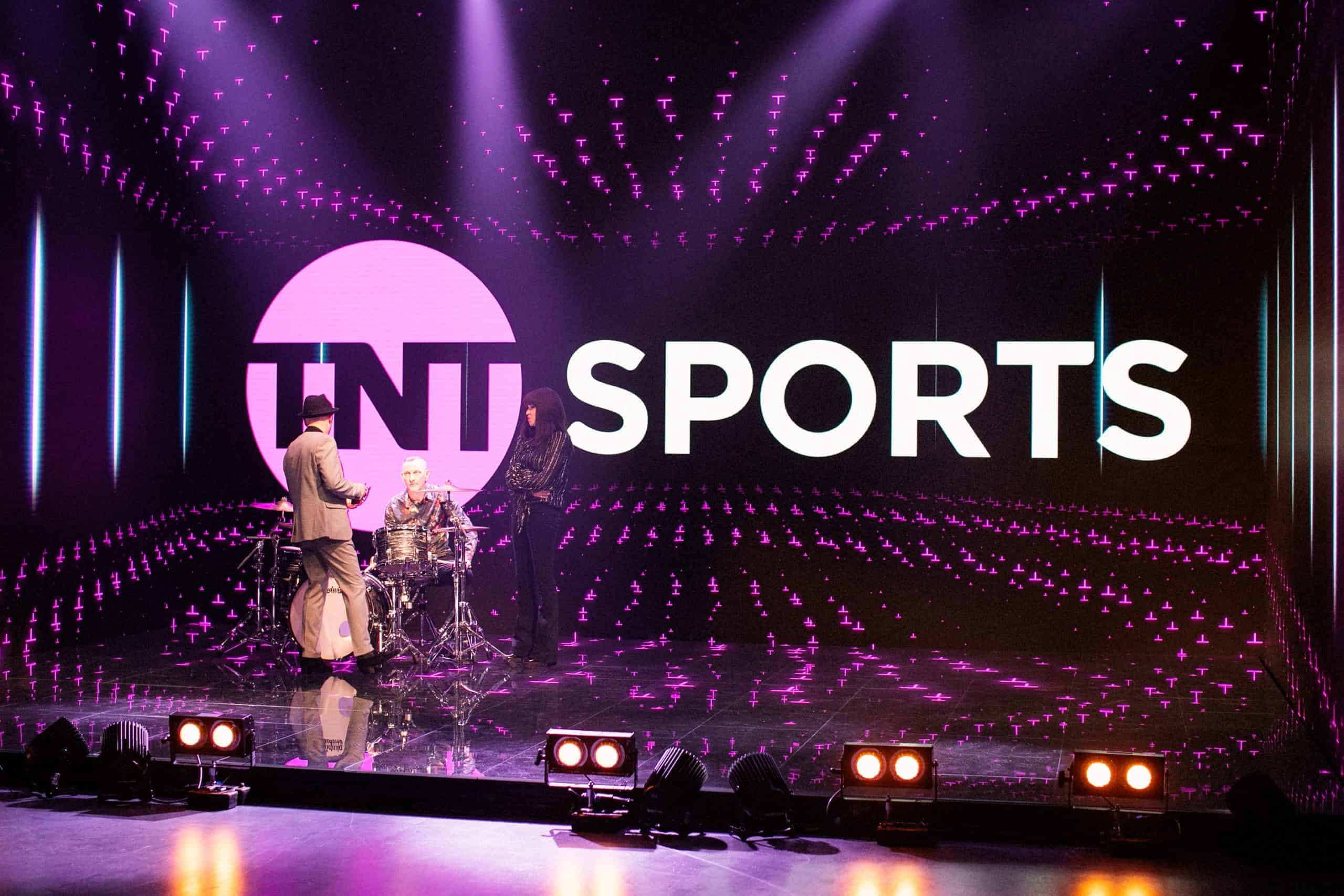
Bad content can make a well-specified LED system look terrible on air. Content for a studio backdrop should be designed for camera sampling from the start — built and reviewed at the wall’s native canvas, then tested through the production chain, not adapted from material made for direct viewing.
- Avoid one-pixel lines and fine grids — they alias against both the wall and the sensor.
- Keep text large if it must appear behind presenters, and assume it will be read at the edge of focus.
- Reduce high-contrast black-white patterns, which exaggerate any residual moiré.
- Use slower motion for background graphics; fast movement behind a static presenter pulls the viewer’s eye.
- Test saturated colours, especially red and blue, at the operating colour space — these sit closest to the gamut boundary.
- Check gradients at operating brightness, not only at full brightness, where banding hides.
- Build safe versions of key graphics for tight camera shots, and keep essential information in areas that stay visible across the planned camera positions.
For presenter-led programming, the wall is usually atmosphere rather than information. If the viewer is genuinely meant to read detailed text, it often belongs in a keyed on-screen graphic or on a dedicated studio display closer to camera, not on the backdrop. The content team should also know the processor canvas and active screen area, so graphics land pixel-for-pixel without avoidable scaling.
Set design carries its share of the result. Glossy desks, polished floors and glass partitions reflect the wall; front light aimed at presenters lifts the apparent black level if it spills onto the LED surface. Coordinating wall angle, masking, scenic finishes and lighting positions preserves contrast without forcing the display to run brighter than it should.
Choosing Your Broadcast Studio LED Backdrop
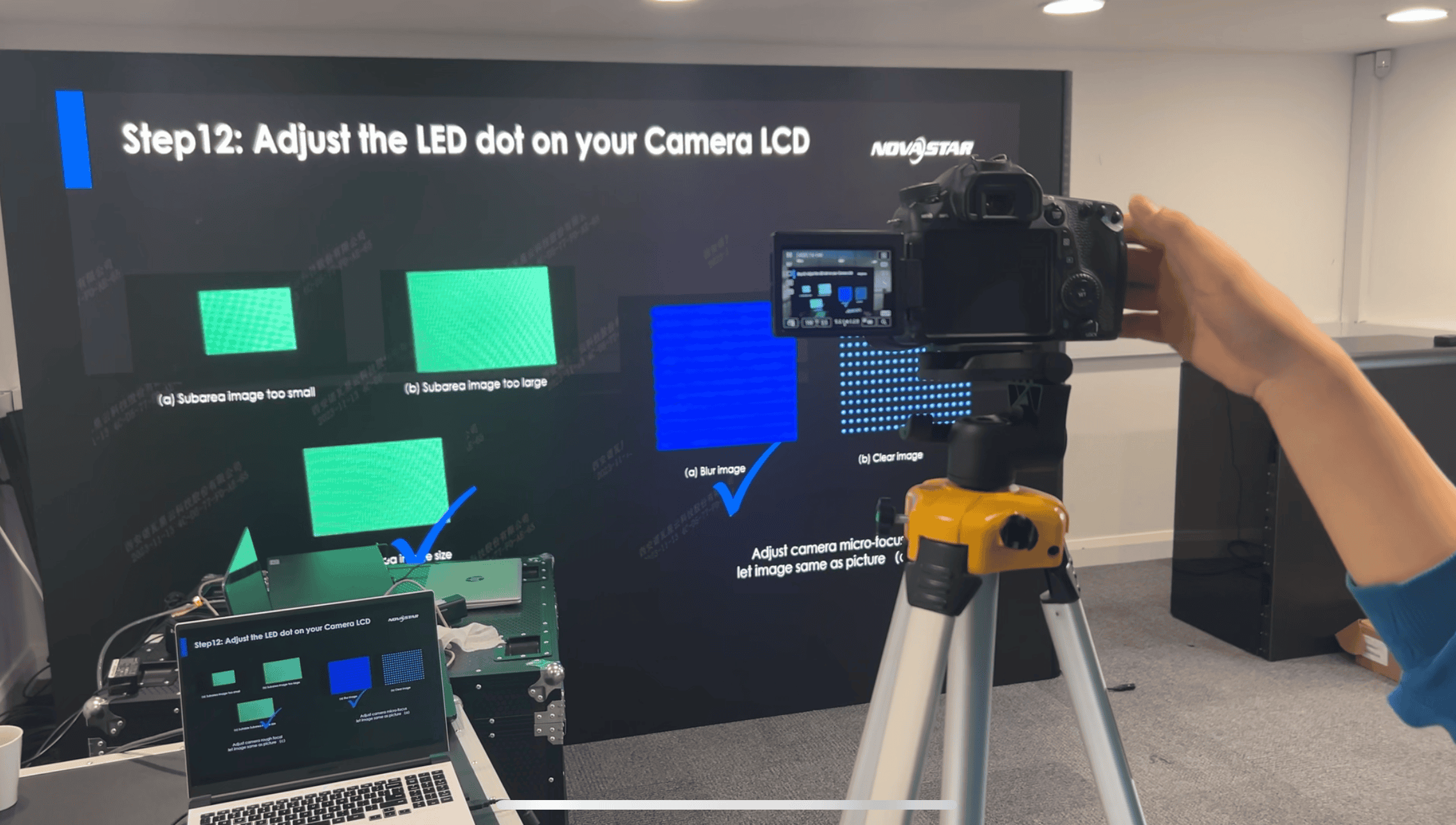
If you are planning a studio, newsroom, sport analysis set or virtual production space, start with the shot list and the signal workflow rather than a square-metre price. Document camera positions, focal lengths, presenter marks, programme formats, reference timing and expected operating hours — that information establishes where pitch, processing, service access and redundancy genuinely affect the production. The hardest shot in the running order sets the pitch; the camera plan sets the sync design; the lighting plot sets the operating brightness. Explore our LED video wall solutions to see how we approach fixed-install studio projects, or send us the shot list and floor plan and we will come back with a specification for the pitch, processor and genlock setup your broadcast studio LED backdrop will need.
From the Field
I have one rule for broadcast studio LED backdrop projects: get engineering and production in the same room early. If I only speak to the set designer, we miss sync and control. If I only speak to engineering, we miss how the director wants to move the cameras. My first question is always about the hardest real shot — closest camera, sharpest lens, deepest focus, brightest graphic. If that shot behaves on a sport analysis set shooting 50i or a regional news studio running 25p, every easier shot follows. The projects that go wrong are the ones specified from a wall size and a budget line, with the camera plan arriving after the panels have shipped.
The other question I always ask is who maintains the wall after handover. A studio technician should be able to identify a failed module, isolate a data issue and reach every serviceable component without dismantling scenery. We document operating brightness, processor configuration, sync settings and approved signal routes at commissioning, so the signed-off picture can be restored after maintenance or a production change — not rebuilt from memory.
Broadcast Studio LED Backdrop: Frequently Asked Questions
What pixel pitch is right for a broadcast studio LED backdrop?
Most presenter-led studio backdrops sit between P1.5 and P2.6. The right pitch depends on the closest camera distance, the lens and whether the wall is held in focus. Close-up work, deep focus and detailed graphics all push the pitch tighter — below P1.2 for sharp-focus shots at around 1.5 metres. A test shoot with the intended camera settings is the safest way to confirm the choice before committing to hardware.
Why does genlock matter for studio LED walls?
Genlock locks the LED wall’s refresh cycle to the camera’s frame rate through a shared sync signal, eliminating horizontal banding and rolling scan lines on air. Without it, the camera shutter captures the wall mid-refresh. The sync plan should be agreed before the processor and signal path are specified — it determines which processor you buy, not the other way round.
What refresh rate should a broadcast LED wall have?
A minimum of 3,840 Hz is the practical baseline. At that rate the wall completes a full refresh roughly 64 times per 60 Hz frame, so the camera never samples a partial refresh regardless of shutter speed. The headline number is not the whole story, though — driver configuration, scan behaviour and operating brightness all influence the recorded result, so test across the production camera presets.
Can I use a rental LED wall as a permanent studio backdrop?
Rental LED suits pilots, temporary sets or short production runs. For a permanent studio we specify a fixed-install product such as the DFC or DX range. Fixed systems are built for sustained daily operation with front-service access, slimmer cabinets, redundant power and data paths, and cleaner scenic integration. Rental cabinets are engineered around repeated assembly and transport — different priorities from a wall that runs on air every day.
How bright should a studio LED backdrop be?
The useful figure is operating brightness under the studio lighting plot, not maximum output. The wall needs to sit behind presenters without overpowering skin tones or forcing awkward exposure settings on the cameras. Most broadcast applications run between 400 and 800 nits, dimmed to 30–50% of the panel’s peak output — which is also why deep greyscale processing matters at low drive levels.
What colour space should a broadcast LED wall be calibrated to?
Rec. 709 for HD broadcast, Rec. 2020 for UHD and HDR production. The LED processor maps the wall’s native gamut to the target colour space so the camera records what the gallery expects. This calibration is separate from basic white balance and should be done with a spectroradiometer by someone who understands the camera system’s colour pipeline.
How deep is a fixed-install studio LED wall?
Flush-mount fixed-install cabinets for studio use run between roughly 37 mm and 50 mm deep. The DFC Series cabinet is 37 mm, which allows direct mounting to a stud wall without a structural recess. Front-service access removes the need for a rear void entirely — every module, power supply and receiving card comes out from the studio floor side.
Conclusion
Every decision here — pitch, sync, colour mapping, content, service access — feeds into the same live shot. The right specification comes from the hardest camera angle in the running order, the actual signal workflow and the content that will run every day, not from a wall size and a price per square metre.
For fixed studios, we steer the conversation towards the DFC or DX ranges depending on pitch, service access and budget. For XR and virtual production, the system design widens to include tracking, rendering and colour workflow. Our Brook Sixth Form XR studio case study shows what that looks like in a school stage, including the tracking and rendering that were left out. In both cases, the earlier we see the shot list and signal path, the fewer compromises appear on site.
Planning a broadcast studio LED backdrop? Tell us about the studio, the cameras and the shots you need to land — get in touch or call us on +44 (0)203 489 9878 and we will talk through pitch, processing and genlock before you commit to a specification. For a three-sided filming build, see the 2mm LED wall Dynamo built for a BT Sport Champions League advert.