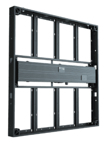
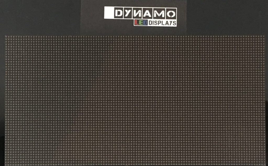
Specifiers ask us the same question in different words: when an LED display goes wrong, what actually breaks? The answer lives on the LED module, the tile-sized board every cabinet is built from. Knowing the LED module components explains why a single dark pixel is cheap to fix, why a dead column points somewhere else entirely, and why the part that fails first is rarely the part people worry about.
Key takeaways
- An LED module is a printed circuit board (PCB) carrying LED lamps, driver ICs, row-switching transistors, passive components and a ribbon connector.
- A 250 mm DX Series module at 2.5 mm carries 100 pixels along each edge: 10,000 lamps and 30,000 dies on one board.
- Lamps fail one pixel at a time, usually from contact. Driver ICs and row-switching transistors fail a line at a time. Ribbon connectors, hub boards and power fail a block at a time.
- Faults scattered at random are electrical. Faults clustered at hand height or floor height mean someone is touching the display.
- Below 2.5 mm, any LED display the public can reach should be GOB or COB, and a spare module must match the original’s electronics and scan configuration, not just its pitch.
At a glance: the module in Dynamo projects
| Item | In practice |
|---|---|
| LED module | The smallest replaceable board in the display, held in by magnets or screws |
| Lamp type by series | SMD1515 and SMD2020 on the DX Series (1.9 mm to 5.9 mm); flip-chip COB on the DFC Series (1.58 mm and 1.9 mm); GOB-protected SMD on the DIT Pro at 1.9 mm |
| Module size and resolution | DX 2.5 mm: 250 × 250 mm, 100 × 100 pixels. DFC 1.5: 304 × 342 mm, 192 × 216 pixels |
| Example install | Auto Trader, Manchester: 1.86 mm flexible tiles and 1.9 mm GOB-protected DX Series panels, all within arm’s reach |
| Most frequent fault | Single dead or wrong-colour pixel from mechanical contact |
| Standard warranty | Three years return to base |
What are the components of an LED module?
An LED module is a PCB carrying LED lamps on the front and driver ICs, row-switching transistors, capacitors, resistors and a ribbon connector on the rear. It is the smallest replaceable unit in an LED display, and it receives power and data from the cabinet’s hub board, which is fed in turn by a receiving card.
- LED lamps, one per pixel, each holding a red, a green and a blue die
- PCB, whose copper tracks and solder joints carry every signal between the parts
- Driver ICs, constant-current chips that set the brightness of each colour on each lamp
- Row-switching transistors, which light one row at a time so a few drivers can serve thousands of lamps
- Capacitors and resistors, which keep supply and signal clean
- Ribbon connector, carrying data and low-voltage DC from the hub board
- Mask or encapsulation: a black plastic mask indoors, potting or conformal coating outdoors
Pitch decides how many lamps the board carries. The DX Series datasheet puts 100 × 100 pixels on a 250 mm module at 2.5 mm, so 10,000 lamps and 30,000 dies sit on a board you can hold in your hand. Our pixel pitch guide covers choosing a pitch, and our COB vs GOB vs SMD guide compares the three ways those lamps can be built and protected.
Lamps: the part that fails one pixel at a time
Ask a repair technician what they replace most and the answer is a lamp. Not because LED dies wear out quickly, but because on a fine-pitch indoor display the lamps are tiny, sit proud of the PCB and have nothing in front of them but air. A finger, a vacuum nozzle or a ladder rail brushing the surface will shear the lamp off or crack a bond wire inside it. The symptom is specific: one pixel goes dark, or loses a single colour and shows the wrong tint against its neighbours. A failed die stays dark at every brightness level. A cracked solder joint comes and goes with temperature. Our DFA outdoor datasheet rates lamp life at 100,000 hours, so on a display run at sensible brightness the lamp is not the lifetime-limiting part.
This is where encapsulation earns its cost. Below 2.5 mm the lamp is small enough that mechanical damage becomes the dominant failure mode, and GOB or COB spreads any impact across a continuous layer instead of one package. On the DFC Series, our premium fixed-install line, the flip-chip COB surface is what lets a boardroom wall take years of cleaning contractors without collecting dead pixels along the bottom row. The trade-off is repair access: an exposed SMD lamp can be reworked on the bench, while a GOB or COB surface usually means the whole module is replaced.
Driver ICs and row-switching transistors: the part that fails a line at a time
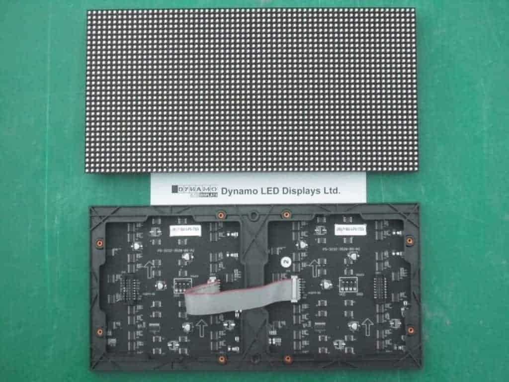
Driver ICs and row-switching transistors fail a line at a time, so a dead row, a dead column or one colour missing along a strip points here rather than at the lamps. Each driver IC is a constant-current device with a set of output channels, and each channel controls one colour on one lamp while that row is switched on. Greyscale comes from pulse-width modulation: the driver switches the die on and off faster than the eye can follow, and the on-to-off ratio sets perceived brightness. Because a module carries far more lamps than any driver IC has channels, row-switching transistors light one row at a time, and the higher the scan rate the smaller the slice of time each row gets. The DX Series datasheet quotes a refresh rate of at least 3,840 Hz and 14-bit greyscale at 2.5 mm, but a headline refresh rate does not tell you how cleanly a module renders a dark grey gradient, so we ask to see neutral greys at the intended operating brightness before accepting a specification on paper.
When a driver channel fails, one colour disappears from a column, or the column goes dark. When a row-switching transistor fails, a row goes dark or sticks on as a bright line. Neither fault has anything to do with the lamps on that line, which is why replacing a lamp never fixes it. The same pattern can come from a wrong scan configuration or a corrupted receiving card file, so we check the configuration history before condemning a component.
Driver ICs fail from static during handling, heat, and transients from a power supply that is starting to go. The ESD Association’s fundamentals explain the first, and its ANSI/ESD S20.20 standard sets out the handling controls we specify for every service visit. A driver swap is a hot-air rework job, so we swap the module on site and rework the board off site. A module built to the IPC-A-610 acceptability standard starts life with far fewer marginal joints.
Ribbon connectors, hub boards and power: the part that fails a block at a time
These are the parts nobody looks at until they fail. A ribbon connector carries data and control from the hub board, with low-voltage DC arriving separately or on the same ribbon. A ribbon connector seated badly at installation, or worked loose by thermal cycling, gives a module that flickers, shows noise or goes dark in one hit. Connectors carry current through small contact areas, so a fraction of an ohm of unwanted resistance at a few amps costs voltage under load and heats the joint. That is why a marginal ribbon connector fails under bright content and looks fine on a static test pattern. A hub board fault takes several modules, and a receiving card fault or lost network link takes the whole cabinet, as our signal chain explainer sets out.
Receiving cards from NovaStar and processors from Brompton both hold calibration data for the modules they drive, so a replacement module needs its own calibration loaded or it sits visibly brighter or cooler than its neighbours. A PSU drifting out of specification rarely fails cleanly either. It can pass ripple through to the driver ICs for months before the cabinet drops out, which is why our outdoor thermal management guide spends as long on PSU placement as on lamp temperature.
Reading the fault from the symptom
Most faults can be located from across the room. The pattern points at the component.
| What you see | Where to look first |
|---|---|
| One pixel dark or the wrong colour | Lamp on that pixel, or its solder joint |
| One colour missing along a column | Driver IC channel on that module |
| A full row dark, or a bright row stuck on | Row-switching transistor, then scan configuration |
| One module flickering, noisy or dark | Ribbon connector, then the module itself |
| Several adjacent modules dark | Hub board or a power feed within the cabinet |
| A whole cabinet dark | Receiving card, network link or cabinet PSU |
| One module a different tint after a repair | Missing or wrong calibration data on the replacement |
That table is the logic our engineers use on a repair visit, and it tells you what to stock: spare modules cover the first four lines, a spare receiving card and PSU cover the next two. If you are seeing one of these on an existing LED display, send us a photo and the result of red, green and blue test patterns and our repair team will name the part before anyone travels.
What this means when you specify an LED display
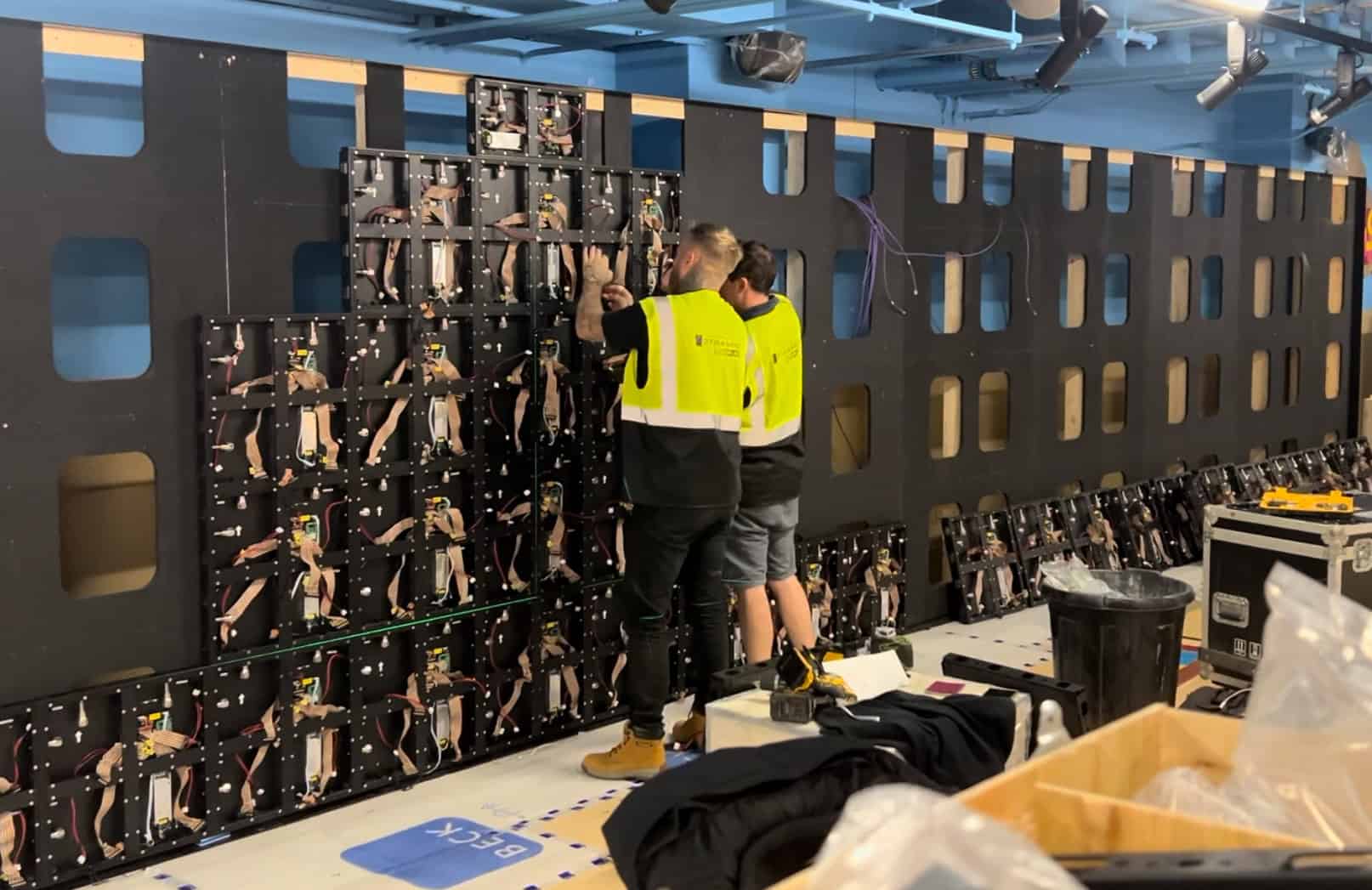
Buy spare modules with the display, not later. Lamps from a later batch will not match the original in brightness or colour temperature, and calibration cannot hide a mismatched module completely. Two boards marked P2.5 are not automatically interchangeable: a spare needs the same dimensions, mounting, connector pinout, supply voltage and scan configuration, so ask for the module revision and configuration files in the handover documents.
Match encapsulation to the environment. Any LED display below 2.5 mm that the public can reach, in a corridor, a retail floor, a school or a showroom, should be GOB or COB. A display above touching height behind a boardroom table can run standard SMD with a mask. For a mid-range fixed install at this pitch, our 2.5 mm direct-view page covers the DX Series options.
Design the cabinet for heat before depth, and keep to the schedule in our maintenance guide: dust on the rear of the module raises driver IC temperature, and loose ribbon connectors show up as intermittent faults long before they fail.
Our LED display range sets out which line fits which installation, and the LED screen configurator gives a starting estimate for a wall size and pitch. For a specific brief, including spares, contact us or call +44 (0)203 489 9878.
From the field
Daniel, Dynamo LED Displays
The faults that have taught me the most are the retail walls where a client logs a steady trickle of dead pixels and is convinced the product is at fault. When I go and look, every one sits in the bottom 300 mm of the display, and every one is a sheared lamp from a floor polisher, a trolley or a pushchair. A low kick rail and a swap from the client’s own spares ends it.
My rule now is that I look at where the faults are before I look at what they are. Scattered faults tell me something electrical is happening. Faults clustered at hand height or floor height tell me someone is touching it. If a client sends me a photo of a dead row, I ask for red, green and blue test patterns and whether anything changed on the processor before I agree which part needs replacing.
LED Module Components: Frequently Asked Questions
What are the main components of an LED module?
An LED module carries LED lamps on the front of a PCB, with driver ICs, row-switching transistors, capacitors, resistors and a ribbon connector on the rear. Indoor modules add a plastic mask over the lamps; outdoor modules are potted or coated. Power and data arrive from the cabinet’s hub board, fed by a receiving card.
Which component fails first on an LED display?
On fine-pitch indoor displays, lamps fail first, almost always from physical contact rather than electrical wear. On outdoor displays and displays driven hard in warm cabinets, driver ICs and power supplies are more likely to go first. Ribbon connector faults are rarer but take a whole module out rather than a single pixel.
Can a single dead pixel be repaired?
Yes. A single dead pixel is a lamp replacement, done on a bench with a hot-air rework station. In practice our LED screen repair engineers swap the whole module on site and repair the original off site, so the display is back to full picture the same day. The replacement needs its calibration data loaded.
Does GOB or COB reduce module failures?
For mechanical damage, yes. GOB pours an epoxy layer over the lamp array and COB encapsulates dies bonded directly to the PCB, so a knock spreads across a continuous surface rather than one lamp. Neither changes the electrical failure modes of the driver ICs or ribbon connectors behind the board, and both make lamp-level repair harder, so hold spares.
Should spare modules come from the same production batch?
Yes. Lamps from a later batch differ in brightness and colour temperature, and even a compatible board can show a tint difference on neutral greys that calibration cannot fully hide. Buy spares with the display, confirm the module revision matches, and store them dry at room temperature.
Conclusion
Every fault on an LED display traces to one of the LED module components on the board or to the path feeding it. Lamps fail a pixel at a time, mostly from contact. Driver ICs and row-switching transistors fail a line at a time, mostly from heat, static or dirty power. Ribbon connectors and hub boards fail a block at a time. Read the pattern, rule out configuration, and the component tells you where it is.
If you are specifying a new LED display or making sense of faults on an existing one, contact us or call +44 (0)203 489 9878 and we will tell you which of the LED module components is at fault.