LED display calibration: a decision‑maker’s guide to image processing and uniformity
Updated September 2026: added a first-hand commissioning example, consolidated the enquiry contact into one block and refreshed the page schema (reviewer named, FAQ and speakable markup). Technical content unchanged.
LED display calibration is the work that makes an LED wall behave like one seamless canvas, rather than a collection of cabinets. In this guide, we explain how calibration fits into the wider image‑processing chain, what to specify, and how to plan commissioning and ongoing upkeep so the picture stays consistent.
Key takeaways
LED display calibration aligns brightness and colour across modules and pixels so the wall looks uniform from edge to edge.
Image processing is part of the same quality outcome as the LED panels, because the controller, receiving cards and driver ICs (integrated circuits) determine how content is rendered.
Pixel‑level calibration often uses a calibrated digital camera system (plus software) to measure the screen and generate correction coefficients for the receiving cards.
Calibration only works if you define clear targets, including colour space and white point, and then validate the result with agreed test patterns and acceptance checks.
A practical handover should include backed‑up calibration data, system configuration files, and a repeatable process for replacing modules without visible colour shifts.
At a glance
Suited to: Buyers specifying LED walls for retail, corporate, events, broadcast, virtual production and high‑impact signage.
What you’ll learn: How processing and calibration affect uniformity, motion, shadow detail and colour intent.
What you’ll need to define: Wall size and layout, pixel pitch, viewing distance, ambient light, content sources, and your colour/brightness targets.
What we assume: You want a predictable, repeatable outcome you can maintain after installation.
What LED display calibration actually means
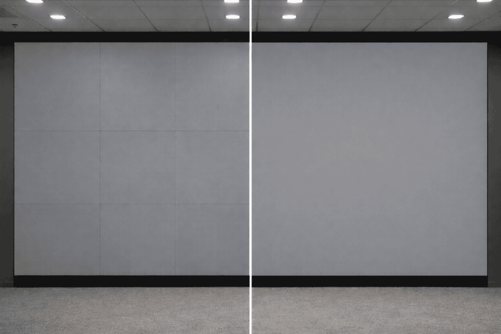
LED display calibration is the process of measuring the screen’s output and applying correction data so brightness and colour are consistent across the whole wall. The practical result is simple: whites look like one white, greys look even, and solid colours do not show seams between cabinets.
In most modern systems, calibration data is stored as coefficients and applied through the LED control system, typically via the receiving cards in the cabinets. NovaStar’s NovaLCT documentation, for example, describes saving, uploading and adjusting calibration coefficients to receiving cards and backing them up to a calibration database file.
Content “grading” or creative colour correction, which happens in your media workflow.
Basic on‑screen tweaks (contrast, colour temperature), which can help but cannot correct pixel‑to‑pixel variation.
A one‑time factory setting, because the final wall arrangement, environment and viewing conditions matter.
A useful way to think about it: factory calibration helps the parts look consistent; on‑site calibration helps the finished wall look consistent.
The image signal chain: where picture quality is won or lost
The signal chain is the set of components that takes your video source and turns it into light from millions of LEDs. A strong panel spec does not guarantee a strong picture if the processing chain is under‑specified or configured incorrectly.
Typical components in the chain
Source devices: media players, laptops, broadcast kit, cameras.
Video processing: scaling, frame rate conversion, colour space handling, latency management.
LED control system: mapping, distribution and driving of pixel data.
Receiving cards and driver ICs: the last stage that controls how each pixel is driven.
At Dynamo, we work extensively with NovaStar and Brompton control ecosystems, because processing and control stability are as important as the LED hardware for predictable results.
Sending cards, receiving cards and driver ICs
A common architecture is:
A sending stage (processor/controller) that outputs LED‑specific data streams.
A receiving card in each cabinet that interprets that data and applies calibration coefficients.
Driver ICs (integrated circuits) on the modules that regulate current and timing to each LED channel.
If you are comparing quotes, one quick quality test is to ask: “Where is calibration applied, and how is it stored and backed up?” If the answer is vague, maintenance and module replacement can become painful.
The quality parameters that matter beyond pixel pitch
Pixel pitch and brightness get the headlines, but decision‑makers usually feel problems in different ways: banding in gradients, odd skin tones, flicker on camera, or visible cabinet seams.
Refresh rate
Refresh rate (measured in Hertz, Hz) is how often the displayed image updates each second. A higher refresh rate can reduce visible flicker and improve how the wall behaves on camera, but it is not a single‑number guarantee of quality.
A practical buying question is: “What refresh behaviour can you demonstrate with our real content and cameras, in our real lighting?”
Grayscale and low‑brightness behaviour
Grayscale depth (often expressed as bit depth) affects how smoothly the wall renders shadows and gradients. In the real world, the challenge is often low‑brightness stability, where shadow detail can get lost if the system cannot drive the LEDs cleanly at small output steps.
If your project includes dark scenes, subtle gradients, or camera capture, ask to see a gradient test pattern and a near‑black ramp during acceptance checks.
Colour accuracy and Delta E
Colour accuracy is often discussed using Delta E (ΔE), which is a measurement of perceived colour difference between a target colour and what is displayed. Lower ΔE values mean the displayed colour is closer to the reference.
We recommend treating ΔE as a project requirement you define (based on brand needs, cameras and lighting), not a marketing number pulled from a brochure.
Calibration methods compared
Different projects need different calibration depth. For example, rental and staging often prioritise fast module swaps, while broadcast and virtual production prioritise pixel‑level uniformity for camera.
Calibration method
What it adjusts
Typical measurement tools
Strengths
Trade-offs
Suited to
Module or cabinet-level calibration
Brightness/colour alignment across modules or cabinets (not every individual LED)
Factory data, control software tools, sometimes camera capture
Faster, practical for field swaps, reduces obvious seams
May not eliminate pixel-level non-uniformity in gradients and near-black
Rental, staging, fast maintenance environments
Point-by-point (pixel-level) calibration
Individual pixel (and often sub-pixel) correction coefficients
Calibrated camera system, imaging colourimeter, or spectroradiometric reference depending on workflow
Highest uniformity potential across the wall
More time and setup; requires careful environment control and data management
High-end install, broadcast, virtual production, camera-critical work
On-screen adjustments
Global image parameters (white balance, brightness, contrast, saturation)
Control software, test patterns
Quick, useful for initial setup and minor tuning
Does not correct per-pixel variation
General signage and non-critical applications
A simple way to decide is to ask: “Is the viewing (or filming) likely to reveal tiny variations between pixels?” If yes, pixel‑level calibration and tighter control of targets becomes more important.
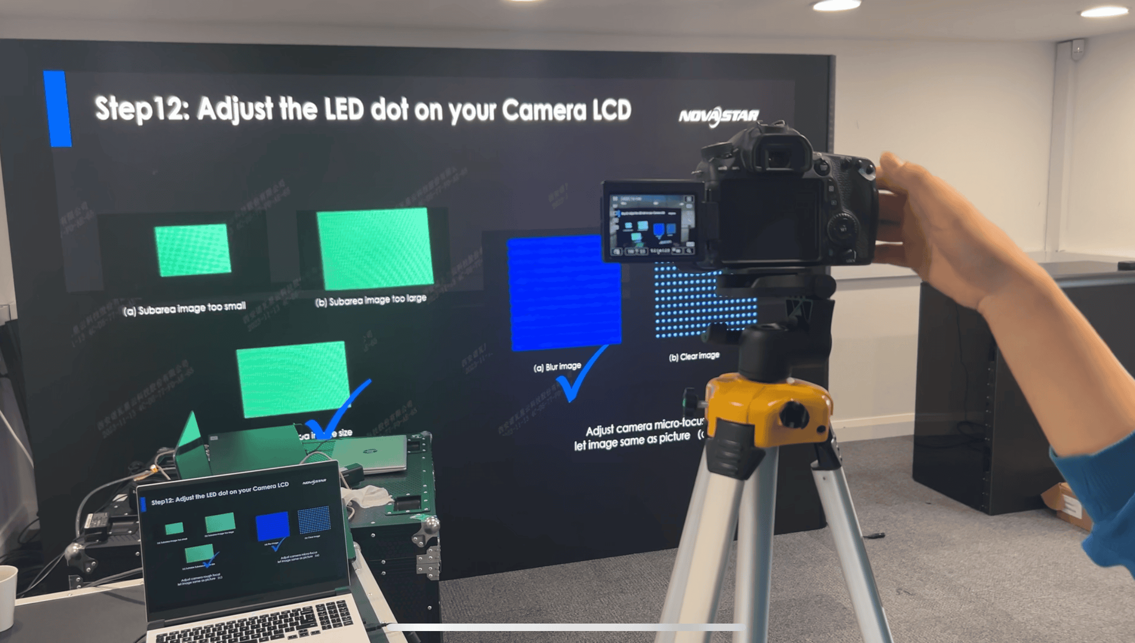
Camera-based calibration: using a digital camera to calibrate LED screens
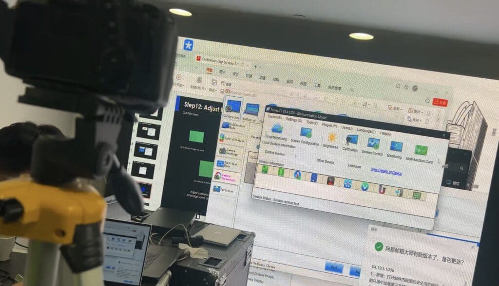
Camera‑based calibration uses a calibrated digital camera system to measure the wall’s brightness and colour output, then generates correction coefficients that the control system applies. This approach is common because it can capture a large number of pixels quickly and consistently.
NovaStar’s pixel‑level calibration documentation includes an equipment list that explicitly references digital cameras (for example Canon DSLR bodies) as part of the workflow.
What to ask for if “camera calibration” is promised
Not all camera‑based calibration is equal. If a supplier says they will calibrate with a camera, we recommend confirming:
Which camera system and calibration software will be used.
How the environment will be controlled (light spill, reflections, access, safety).
Whether the process is cabinet‑level or pixel‑level.
How calibration data is stored and backed up, and what happens when a module is replaced.
Brompton note: camera systems in dynamic calibration workflows
Brompton’s documentation for Dynamic Calibration states that panels need to be calibrated using a camera system as part of that workflow (Brompton refers to its Hydra Camera System).
Setting calibration targets: white point, brightness and colour space
Calibration only makes sense when you define a target. The most common problems we see are not “bad LEDs”, but unclear targets and mismatched assumptions between content creation, processing and the final environment.
A reliable starting point is to document:
Colour space target: for example, Rec. 709 for HDTV‑style content pipelines, or another defined space for your workflow.
White point: commonly D65 in video contexts.
Brightness target: a cd/m² (nit) target appropriate to your ambient light and viewing distance.
ITU documentation describes Rec. 709 and Rec. 2020 displays as using a D65 white point within that definition.
Content sources and formats: HDMI , SDI , playback system , resolution , frame rate .
Preferred look: neutral/accurate or creative bias (both are valid when documented).
Commissioning and calibration: our on-site workflow
Commissioning is the process of configuring, checking and validating the LED system so it performs predictably with your content. A good commissioning workflow is repeatable, documented and safe.
A typical commissioning sequence looks like this:
Physical checks
We confirm cabinet alignment, power and data integrity, and that the wall is clean and secure.
Mapping and topology validation
We confirm pixel mapping and cabinet addressing so test patterns land exactly where expected.
Baseline image processing setup
We set scaling behaviour, input formats, and any colour space handling required for your sources.
Calibration capture and coefficient generation
We run the selected calibration method (cabinet or pixel level) using the appropriate measurement tools.
Upload and backup of calibration data
We ensure coefficients are applied correctly and backed up. NovaStar’s NovaLCT manual describes both uploading coefficients to receiving cards and saving them to a database file for future use.
We run agreed test patterns, gradients and real content clips, then document results and settings.
A good commissioning outcome is not just “it looks good today”, but “we know how to keep it looking good next month and next year.”
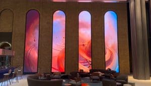
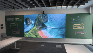
A recent example of this workflow at scale: at AutoTrader’s Manchester headquarters we commissioned five LED zones, including a 21,760 × 1,120 mm double-curved P1.86 mm ribbon (11,696 × 602 px) and P1.9 mm GOB-protected walls, in just under two weeks on a live site, with the configuration and calibration data backed up at handover.
Ongoing maintenance: keeping the wall consistent over time
LED walls change slowly with use, environment and replacement parts. Routine checks reduce the chance of colour drift, uneven brightness and visible seams creeping back in.
A practical maintenance plan usually includes:
Visual checks with test patterns (white, grey ramps, solid colours, checkerboards).
Configuration backups (processor/controller configuration and calibration databases).
Spare module strategy (and a defined process for recalibration after replacements).
If you replace receiving cards or modules, having the correct calibration data and a defined “set coefficients” workflow matters. NovaStar’s documentation describes setting coefficients for new receiving cards and modules by referencing calibration databases or surrounding areas.
Recalibration frequency depends on how critical uniformity is and whether the wall is filmed. As a starting point, we often see:
Camera‑critical work: more frequent checks and recalibration as needed.
Retail and corporate: periodic checks to maintain brand consistency.
General signage: recalibrate when you see drift, after repairs, or on an annual service.
If you want a specific schedule, we recommend agreeing it in your support plan, based on real operating hours, environment and whether the wall is camera‑facing.
Common pitfalls (and how we avoid them)
Most calibration problems are avoidable with a clear spec and a tidy handover. These are the issues we see most often:
Unclear targets
Fix: document colour space, white point and brightness target before calibration.
No backup of calibration data
Fix: keep backed‑up calibration databases and controller config files as part of handover.
Assuming “on-screen adjustments” are calibration
Fix: use on‑screen adjustments for tuning, but do pixel/cabinet calibration when uniformity is a requirement.
Replacing modules without a calibration plan
Fix: use module‑level workflows for fast swaps or plan a pixel‑level recalibration window.
Ignoring the environment
Fix: manage reflections, ambient light and viewing angles, and validate with real content.
Procurement checklist: what to ask for in a quote
If you want consistent results, the easiest place to fix issues is the proposal stage. We recommend asking suppliers to confirm:
Image processing and control
Which control platform will be used (for example, NovaStar or Brompton) and why.
How scaling, frame rates and colour space conversion will be handled for your sources.
Confirm end‑to‑end latency (input → LED emission) in milliseconds for each source type (HDMI/SDI/NDI, etc.), and whether any low‑latency/bypass modes are required.
Confirm whether genlock/frame synchronisation is required for broadcast/IMAG/VP workflows, and how synchronisation is achieved end‑to‑end (processor, cameras, playback, LED controller).
Calibration scope
Whether calibration will be cabinet‑level or pixel‑level.
Whether calibration will be done on-site and what site access is needed (distance, tripod space, safe working).
What measurement tools will be used (camera system, colourimeter, spectroradiometric reference) and what validation patterns will be run.
Calibration coefficients are typically applied through the control system and receiving cards.
Handover deliverables
Calibration database backups and configuration files.
A written process for replacing modules or receiving cards without visible mismatches.
Support plan options and response times.
From the field (Daniel Reynolds, Managing Director)
When we commission an LED wall, we do not start by chasing settings. We start by agreeing the target: what “correct” looks like for your content, your room lighting, and whether the screen is being filmed. Once that target is clear, calibration becomes a controlled process rather than guesswork.
The biggest practical win we see is simple: back up the calibration data and configuration properly. It turns a future module replacement from a stressful visual mismatch into a repeatable maintenance task.
Related Dynamo resources
If you want to go deeper, these are pages we typically point clients to during specification and commissioning:
Talk to us about your LED display calibration requirements
If you are specifying a new wall or you need an existing wall to look more uniform on camera or in‑person, we can help you define targets, plan commissioning, and set up a maintainable calibration workflow.
We operate from London and Oxfordshire and support LED projects across the UK. Our standard purchase warranty is a 3‑year return‑to‑base warranty, and service contracts with a 24–48 hour response can be discussed on request.
What is LED display calibration?
LED display calibration is the measurement and correction of brightness and colour so an LED wall appears uniform across cabinets and pixels, rather than showing seams or colour shifts.
Do we still need on-site calibration if the panels are factory calibrated?
Usually yes, because the final wall layout, cabinet mixing, ambient light and viewing conditions can change the result, and on-site calibration validates the complete installation.
How does camera-based LED calibration work?
A calibrated digital camera system captures the wall’s output, software calculates correction coefficients, and the LED control system applies those coefficients through the receiving cards.
What’s the difference between a colourimeter and a camera in calibration?
A colourimeter measures colour at a point, while a camera-based system can capture many pixels quickly. The right choice depends on the workflow, required precision and how the calibration system is designed.
Does calibration reduce maximum brightness?
It can, because uniformity often means limiting brighter pixels to match the dimmest areas. The goal is a consistent picture, not the highest single-pixel brightness.
How often should an LED wall be recalibrated?
It depends on how critical uniformity is, whether the wall is filmed, and how the wall is used. We recommend setting a review cadence and recalibrating after repairs or visible drift.
Can we mix older and newer LED cabinets on the same wall?
It is often possible, but you should expect additional calibration work when installing to minimise visible differences, and you should confirm how replacements and coefficient management will be handled.
What should we receive at handover to keep calibration maintainable?
Ask for backed-up calibration databases, configuration files, and a documented process for replacing modules or receiving cards without creating visible seams.
About this guide (trust and editorial)
Author: Daniel Reynolds, Managing Director, Dynamo LED Displays.
Technical reviewer: Tristan Grant, Senior LED Engineer, Dynamo LED Displays.
Published: 10 February 2026
Last updated: 2 September 2026
Daniel Reynolds
Daniel Reynolds is Managing Director and founder of Dynamo LED Displays (est. 2013). He leads the specification and delivery of LED display solutions, with expertise in IP networking and both synchronous and asynchronous LED video systems across a range of control environments, including NovaStar and Brompton. Daniel also works as an LED consultant on international projects, supporting clients with system design, technical due diligence, and delivery planning.