Custom LED arches at 40 Leadenhall, London
At 40 Leadenhall in London’s financial district, we delivered four bespoke LED (Light‑Emitting Diode) arches recessed into the building’s main foyer walls. This case study explains what we installed, why the system was engineered the way it was, and the practical specification details that make (or break) architectural LED features.
If you’re an architect, developer, consultant, fit‑out contractor, or AV (audio‑visual) team working on a similar integration, you’ll find checklists and “what-to-decide early” guidance you can reuse on your own project.
Key takeaways
Architectural LED features work best when the aperture, structure, servicing access, and content mapping are designed together from day one.
Fine‑pitch LED (for example, ~1.9 mm pixel pitch) supports close-view detail, but it increases tolerance, calibration, and content‑testing requirements.
Recessed displays need a clear maintenance route (front or rear access), planned cable paths, and ventilation allowances before the walls are closed.
Custom shapes often require bespoke cabinets, non-standard module layouts, and sometimes custom PCBs (printed circuit boards) to match curvature and minimise visible seams.
The playback chain (media server + video processor) must be configured to match the LED pixel map, refresh strategy, and content resolution to avoid artefacts and scaling issues.

Project facts
Location: 40 Leadenhall, London (UK)
Environment: Main foyer (indoor architectural integration)
Screen type: 4× custom LED arches recessed into the walls
Per‑arch size / format: 7.38 m (H) × 1.488 m (W)
Display depth: 50 mm (as built into the wall recess)
LED series / pixel pitch: Dynamo DRA Series, 1.9 mm
Resolution per arch: 768 px (W) × 3840 px (H)
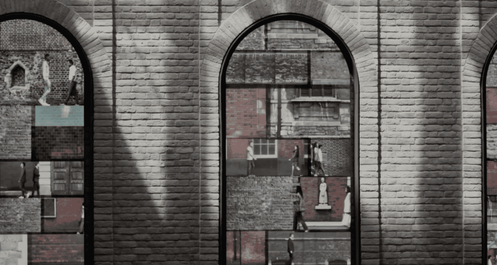
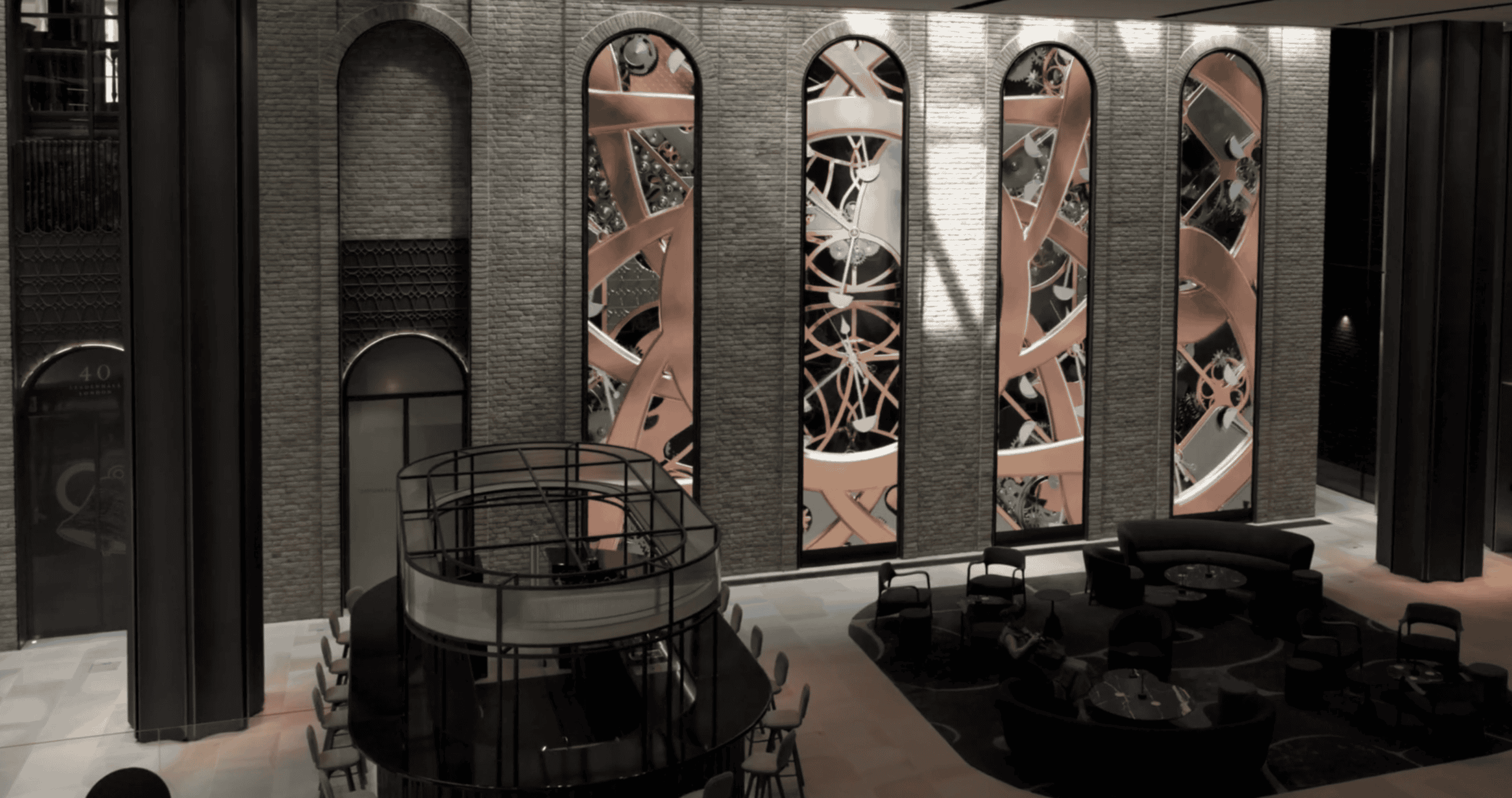
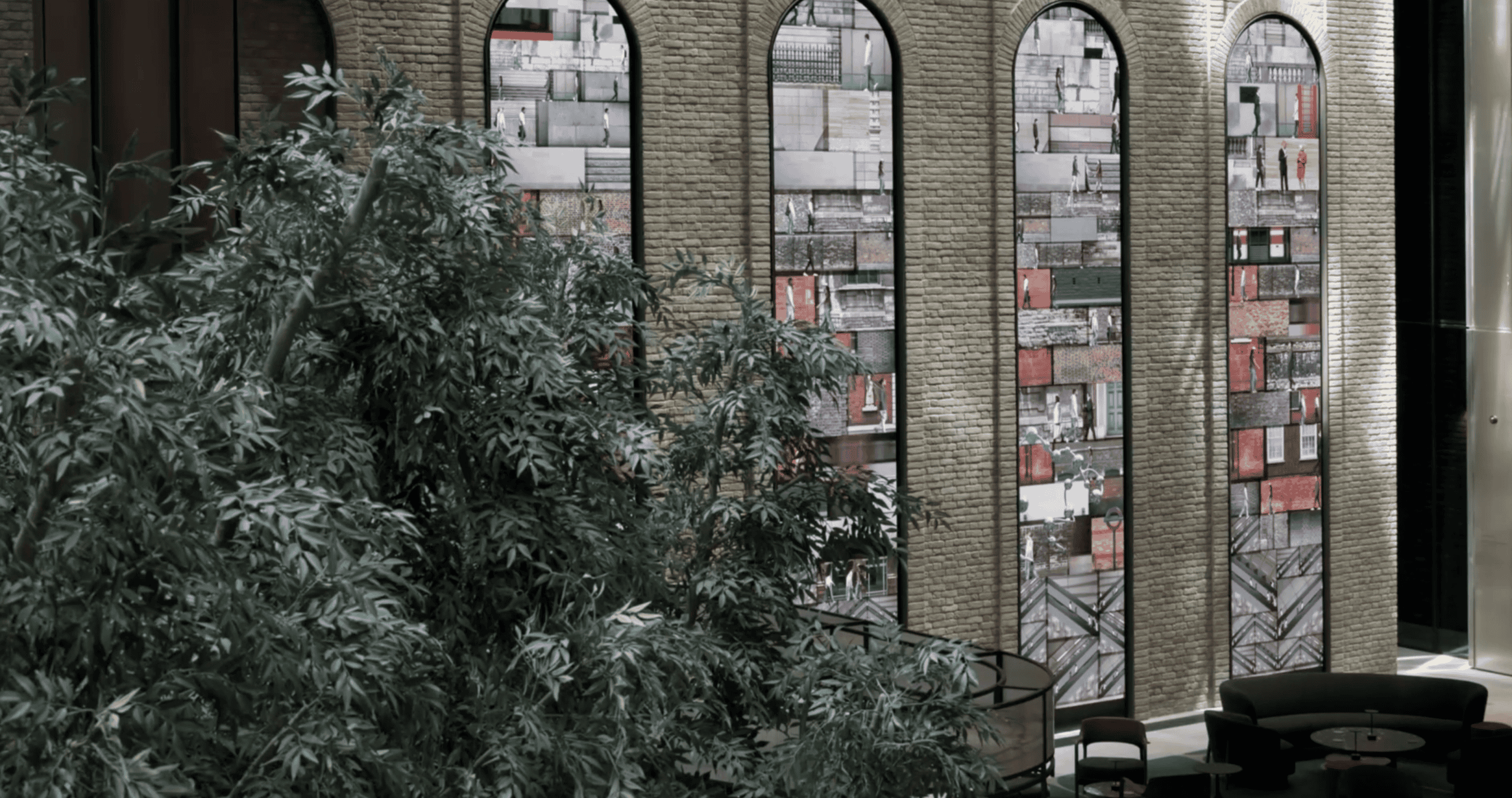
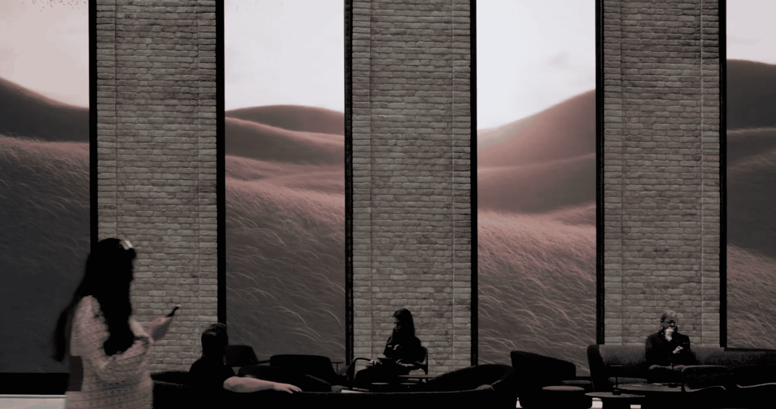
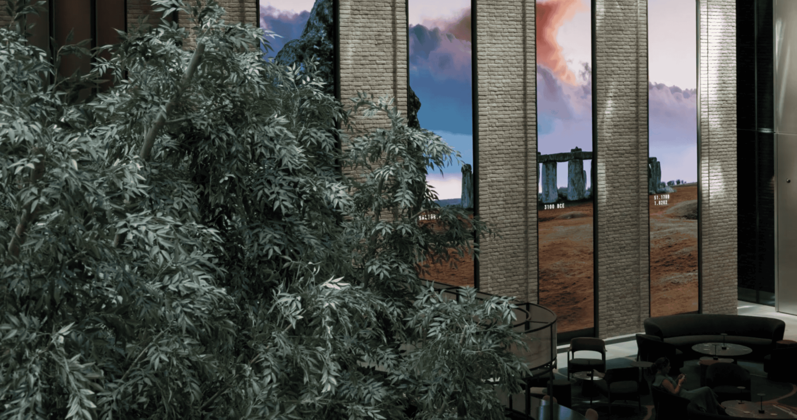
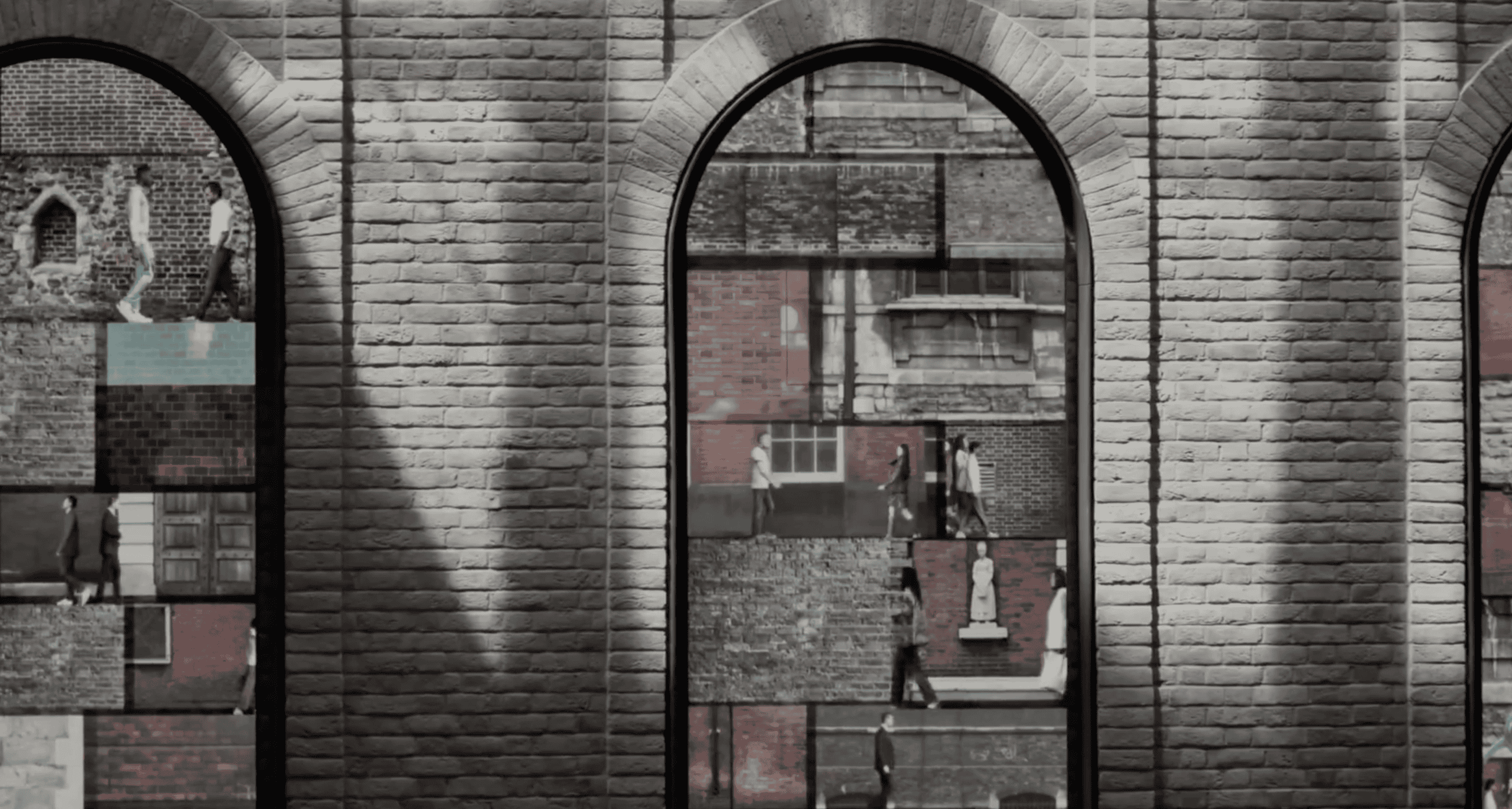
Goal: Create a “digital Georgian window” effect while keeping the installation slim and architecturally aligned
Control / processing: NovaStar H2 video processor + PIXERA media server on a DVS 4U SWARM4-2C4K10G-A4000 Pro+ interactive PC
What the design team wanted to achieve
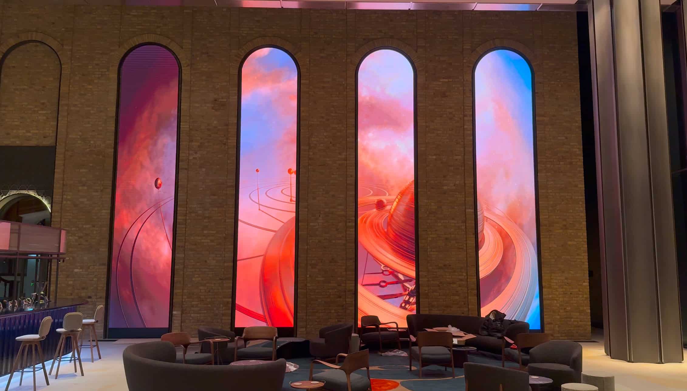
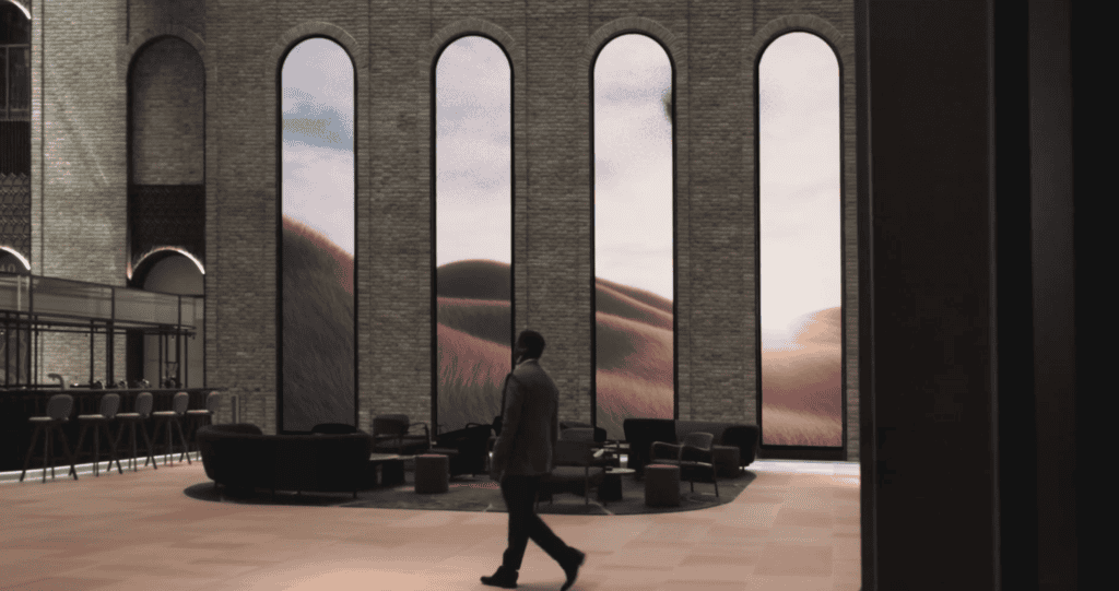
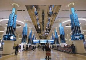
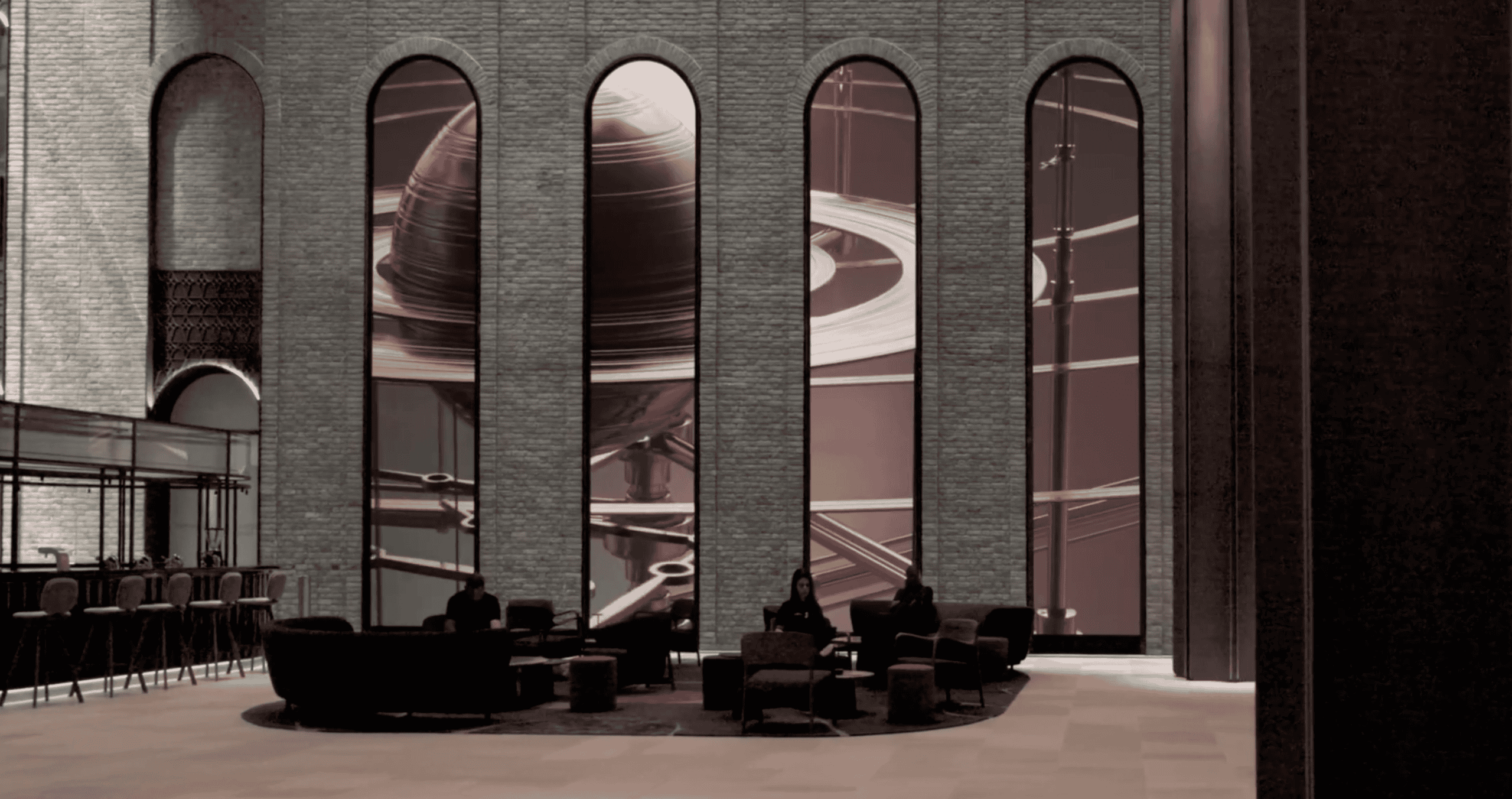
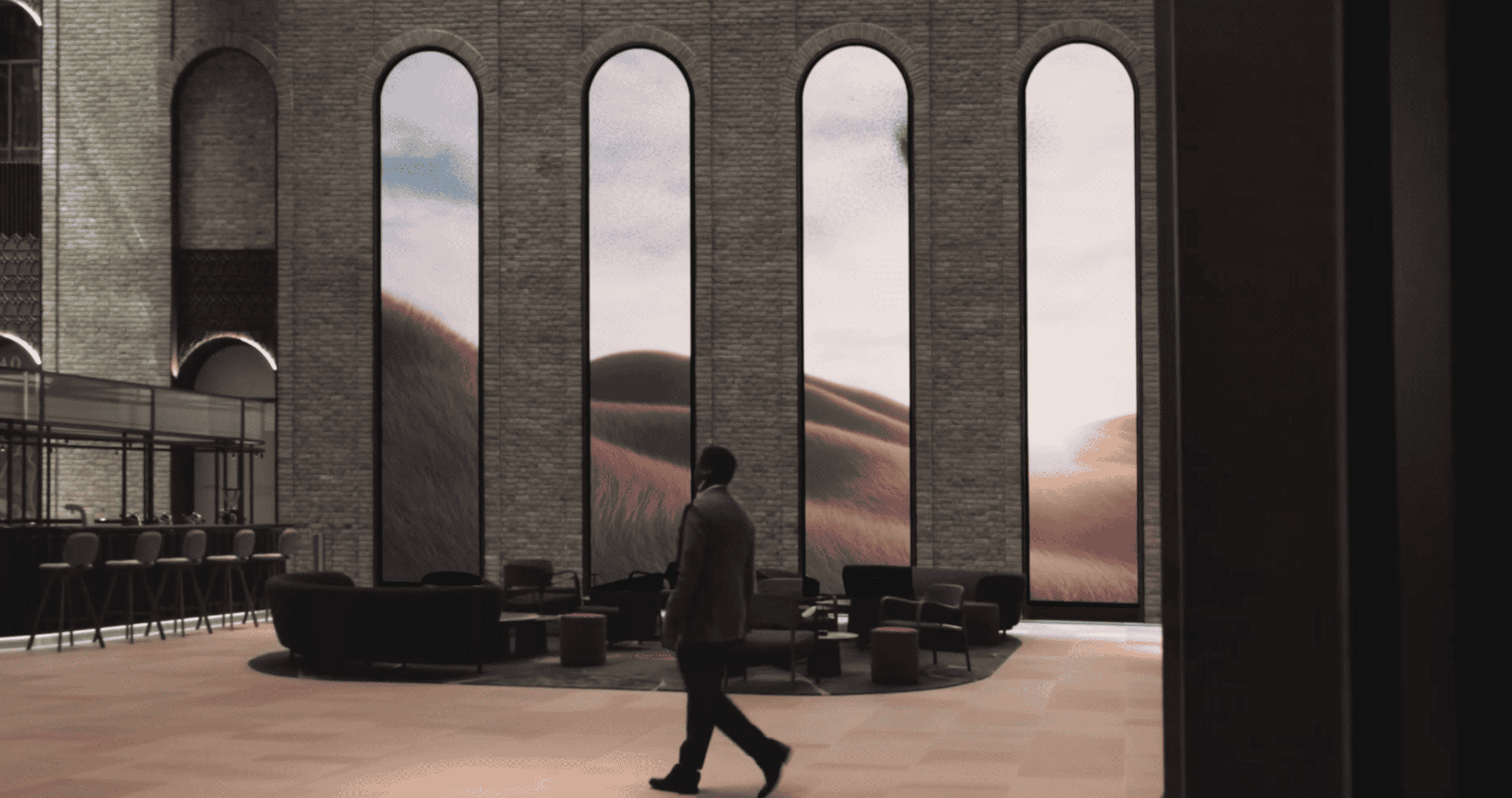
The core idea was simple: create four tall, arched “windows” that look like part of the building fabric, but behave like a dynamic digital canvas.
That meant the LED couldn’t feel like a bolted‑on screen. It needed to be flush, consistent, and visually calm, while still supporting high‑detail content at close viewing distances.

What we installed at 40 Leadenhall
Four recessed arches engineered around the building
Each arch is 7.38 metres high and 1.488 metres wide, with a 50 mm overall depth allowance within the wall build‑up.
Because the arches were recessed into the walls, the work was as much about integration and tolerances as it was about pixel pitch.
LED technology and mapped resolution
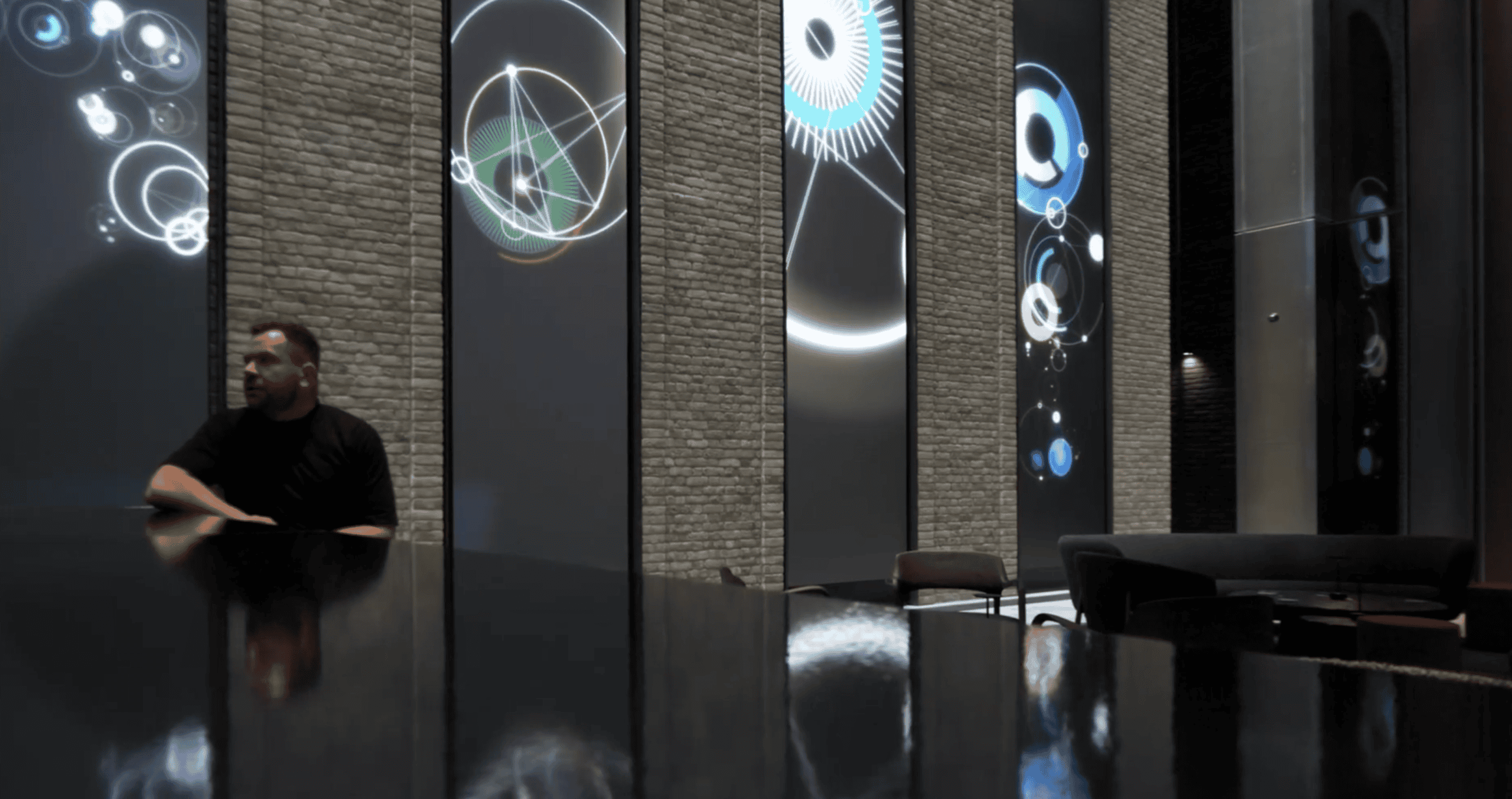
The project used our DRA Series 1.9 mm LED.
Each arch was mapped as 768 × 3840 pixels, which gave the design and content teams a consistent canvas for animation, motion graphics, and imagery without relying on guesswork.
Surface finish and performance tuning
A resin-covered LED surface was specified on this project to support:
controlled reflections and perceived contrast in the foyer lighting,
improved protection for the LED face during operation and cleaning,
stable presentation of colour and greyscale gradients when content sits close to black.
(Resin protection is not “one-size-fits-all” — it’s a design choice that depends on environment, cleaning needs, and the desired finish.)
Processing and playback workflow
This system was powered by:
a NovaStar H2 video processor,
a PIXERA media server,
running on a DVS 4U SWARM4-2C4K10G-A4000 Pro+ interactive PC.
In plain terms:
the media server is responsible for timeline-based playback, show control, and content management,
the video processor handles signal management, pixel mapping, and the final output chain into the LED receiving system.
For bespoke shapes, that pixel map alignment is not optional. It’s what keeps content looking intentional rather than “stretched to fit”.
Technical snapshot
| Item | 40 Leadenhall (this project) |
|---|---|
| Display format | 4 × recessed LED arches (bespoke build) |
| Per-arch dimensions | 7.38 m (H) × 1.488 m (W) |
| Depth allowance | 50 mm |
| Pixel pitch | 1.9 mm (DRA Series) |
| Resolution per arch | 768 × 3840 pixels |
| Processing | NovaStar H2 video processor |
| Playback | PIXERA media server on DVS 4U SWARM4-2C4K10G-A4000 Pro+ PC |
| Integration | Curved cabinets/modules recessed into architectural wall build-up |

The engineering challenges behind “simple-looking” arches
1) Slim depth changes everything
A 50 mm depth target influences almost every decision:
mechanical structure and fixing strategy,
cable routing and connector clearance,
ventilation and heat management,
and (crucially) how the system will be serviced after handover.
When depth is tight, we plan serviceability from the start so maintenance doesn’t become “remove part of the wall”.
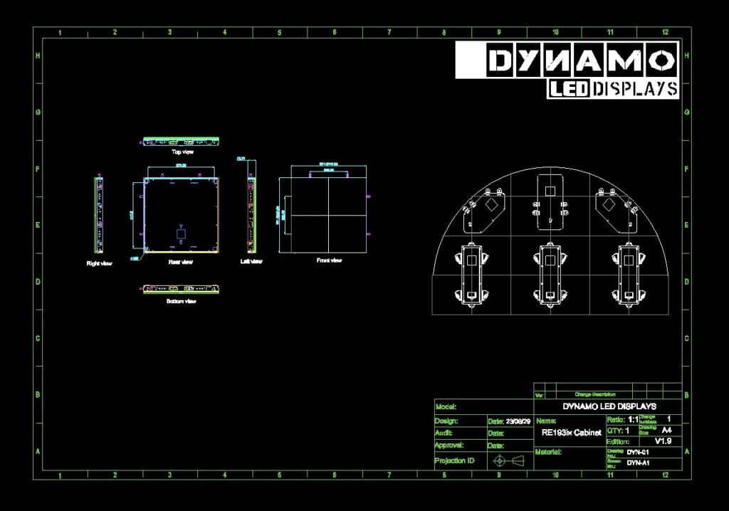
2) Curvature requires more than bending a frame
On a project like this, “curved” isn’t just a cosmetic detail.
To match the curvature precisely, we designed and manufactured bespoke curved cabinets/modules, including custom circuit boards (PCBs) to support the geometry.
3) Architectural tolerances must be agreed early
Recessed LED is only as good as the surrounding build.
Before installation, we align on:
datum points and “finished face” targets,
acceptable tolerance bands (and where they sit),
what happens at edges and returns,
and what access remains once finishes are complete.
4) Non-rectangular content needs a proper mapping plan
Custom shapes typically require:
an agreed pixel map (what the content team builds to),
test patterns that confirm geometry and scaling,
and a commissioning process that checks seams, gradients, and movement.
This is where a media server workflow helps: it keeps creative intent intact while the technical system handles the complexity.
How to specify a recessed or custom‑shape LED feature
If you’re writing an RFP (request for proposal) or developing Stage 3–4 design information, this is what we recommend specifying up front.
| What to specify | What we typically need | Why it matters |
|---|---|---|
| Exact visible aperture (W × H) | Finished opening size + drawings/3D model | Defines module layout, trims, and edge alignment. |
| Depth allowance | Max depth behind finished face + restrictions | Impacts structure, connectors, ventilation, and service route. |
| Curvature | Radius/geometry + tolerance expectation | Determines cabinet design and whether custom electronics are required. |
| Service strategy | Front or rear maintenance + access panels | Prevents “no way to replace a module” issues after handover. |
| Content workflow | Static signage vs timeline playback vs interactive | Drives processor/media server choice and system architecture. |
| Power and data routing | Supply locations, containment routes, comms rooms | Avoids last-minute cable compromises that harm reliability and finish. |
| Acceptance tests | Test patterns, seam checks, gradient checks, “sign-off” criteria | Reduces delays and makes quality measurable. |
ROOM SIDE (public/visible) →
┌───────────────────────────────────────────────────────────────┐
│ [1] Finished wall face (plaster/stone/metal cladding) │
│ - Set your finished datum and edge alignment here │
└───────────────┬───────────────────────────────────────────────┘
│
▼
┌───────────────────────────────────────────────────────────────┐
│ [2] Recess / shadow gap / trim detail │
│ - Defines the “picture frame” and hides tolerance │
└───────────────┬───────────────────────────────────────────────┘
│
▼
┌───────────────────────────────────────────────────────────────┐
│ [3] LED face (modules / protective surface as specified) │
│ - Aim for flushness + consistent edge return │
└───────────────┬───────────────────────────────────────────────┘
│
▼
┌───────────────────────────────────────────────────────────────┐
│ [4] LED cabinet body (depth allowance confirmed in drawings) │
│ - Structure, power, receiving electronics (as applicable) │
└───────────────┬───────────────────────────────────────────────┘
│
▼
┌───────────────────────────────────────────────────────────────┐
│ [5] Cable routing zone (power + data + strain relief) │
│ - Allow connector clearance + minimum bend radius per spec │
└───────────────┬───────────────────────────────────────────────┘
│
▼
┌───────────────────────────────────────────────────────────────┐
│ [6] Ventilation / airflow path (keep unobstructed) │
│ - Intake → across cabinet → exhaust (agree with M&E) │
└───────────────┬───────────────────────────────────────────────┘
│
▼
┌───────────────────────────────────────────────────────────────┐
│ [7] Access strategy (choose one early) │
│ A) Front-service: modules removed from room side │
│ B) Rear-service: walk-in / access void behind wall │
└───────────────────────────────────────────────────────────────┘
→ SERVICE SIDE (mechanical & electrical (M&E) / access void / comms)
Safety and programme notes (UK context)
Architectural LED installs often involve working at height, lifting, temporary works, and multiple trades operating in a constrained area.
If you’re planning a project of this kind, the HSE’s working at height guidance is a useful starting reference:
https://www.hse.gov.uk/pubns/indg401.htm
If the LED will be filmed (or appear on camera)
Even if a project is “just” a foyer feature, it can end up in marketing videos, press coverage, or broadcast.
If on‑camera performance matters, we recommend:
agreeing camera requirements early,
doing a realistic camera test with representative content,
and confirming refresh/scanning behaviour and system settings during commissioning.
Brompton has a clear explainer on the topic (useful even if your processing is not Brompton):
https://www.bromptontech.com/lets-talk-about-moire/
From the field (Daniel Reynolds)
On projects like 40 Leadenhall, the biggest delays usually come from missing decisions, not missing equipment. Depth, access, and “what the finished edges do” all need to be locked early — otherwise you end up redesigning around finishes that are already built.
We also see a lot of content issues when the pixel map isn’t agreed early. If the creative team is guessing the canvas, you get avoidable compromises (stretching, cropping, awkward dead areas). A short mapping and test-pattern session before content production saves days later.
Related services and internal links
If you’re exploring a similar concept, these pages may help:
Bespoke builds: /custom-led-displays/
Architectural project examples: /our-work/
Indoor LED systems: /indoor-led-displays/
Interactive content and sensing options: /interactive-led-display/
Company and engineering approach: /about-us/
Talk to Dynamo: /contact-us/
Next steps
If you’re developing an architectural LED feature — arched, curved, recessed, or otherwise non-standard — we’re happy to review drawings and talk through feasibility, servicing, and the control/content workflow.
Social:
https://www.instagram.com/dynamoleddisplays/
https://www.facebook.com/DynamoLED
https://twitter.com/DynamoDisplays
https://www.youtube.com/@dynamoleddisplays
If you’d like, we can also share images of similar architectural projects we’ve delivered and advise on the most practical route from concept to commissioning.
External references
HSE working at height guide: https://www.hse.gov.uk/pubns/indg401.htm
Brompton Technology (LED on camera): https://www.bromptontech.com/wp-content/uploads/2022/03/Article_Getting-Started-with-LED-on-Camera-1.pdf
Brompton Technology (moiré overview): https://www.bromptontech.com/lets-talk-about-moire/
NovaStar H2 specifications (PDF): https://oss.novastar.tech/uploads/2022/07/H2-Video-Wall-Splicer-Specifications-V1.6.0.pdf
- Press Coverage https://www.inavateonthenet.net/news/article/dynamo-led-displays-delivers-digital-experience-inside-london-skyscraper
FAQs Regarding The Custom LED Arches at 40 Leadenhall
What is pixel pitch on an LED display?
Pixel pitch is the distance between LED pixels, usually measured in millimetres. Smaller pixel pitch generally supports closer viewing and finer detail, but it can increase cost and precision requirements.
How do you specify a recessed LED display so it remains serviceable?
Decide whether the system will be front‑service or rear‑service and keep a clear access route. Include access panels and cable/connector clearances in the wall build‑up before finishes are completed.
Do curved or arched LED displays require custom hardware?
Often, yes. Curved or arched formats may need bespoke cabinets, special module layouts, and in some cases custom PCBs (printed circuit boards) to follow the geometry reliably.
What’s the difference between a video processor and a media server?
A video processor manages the signal chain, scaling, mapping, and LED output. A media server manages content playback, scheduling/timelines, and show control (especially helpful for complex formats).
How do you avoid visible artefacts when LED will be filmed?
Plan a camera test and ensure refresh/scanning behaviour is suitable for the camera. If required, use processing features such as genlock and phase adjustment (where supported) and validate with representative content. Always sync the refresh output, FPS (frames per second) and signal source to the same Hz (or multiples).
What should be included in LED commissioning for architectural installs?
At minimum: pixel mapping confirmation, seam checks, gradient/greyscale checks, colour calibration, movement tests, and an agreed sign‑off pack that documents system settings and access routes.
What warranty does Dynamo provide for purchased LED systems?
Our standard purchase warranty is 3‑year Return‑to‑Base (RTB) although this can be extended. Full service contracts with 24–48 hour response options are available on request.
Written by: Daniel Reynolds — Managing Director, Dynamo LED Displays (IPAF, PASMA, CSCS).
Technically reviewed by: Tristan Grant — Senior LED Engineer.
Original publication date (site): 11 February 2025.


